Thursday, September 23, 2010

Riding, Instruments, & Batteries

School is occupying most of my time, but I've worked in plenty of motorcycling and a lot has occurred in the last month.

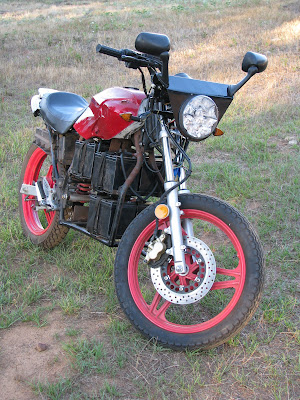
The thing is a joy to ride. I know I already tried to describe the sound, but it's such a cool whirring noise. "Idling" at stop lights is completely silent and really makes it stand out when somebody knows better. It's a real attention-getter in general too, because even though people may not recognize it as being electric, they know something is missing, or changed, or totally different about it. Makes for an easy conversation starter, really. As you can see below, I've put 120 km on it so far, which is 74 miles.

Hardware:
I had a few mechanical issues early on. The rear hub is attached to the rear sprocket with four bolts. The nuts are captured in the hub. When I originally tore the rear hob down, I had to fight two bolt-head-locking washers. Each washers secures a pair of adjacent bolts by going on before the sprocket (acting as a washer of sorts) and then being force-formed around the head of the bolts (acting as a bolt-head-lock) to keep them from turning. Long story short, I completely forgot about them in re-assembly and they most definitely serve a purpose. I lost several bolts out of the hub (banging up the swing-arm, the hub, and the sprocket in the process) and unknowingly, barely made it home once or twice. What a mess - I felt stupid.

Gearing:
Meanwhile, I was also finding out that my gear ratio was not going to suffice. The rear sprocket was kind of a random find, so we just went with it because it was easy to make it work. A little measuring, welding, and painting and suddenly, it was ready. We either forgot to adjust the desired number of teeth for the front sprocket, or again went with what was readily available locally. At the time the bike was licensed for use, the rear was a 68-tooth and the front, a 12-tooth. That's a ratio of 5.667:1. That's pretty steep. Having very little experience on any kind of motorcycle, I was still impressed with it's power and ability, but as I tested the top speed, it became obvious this ratio wouldn't meet my long-term requirements. The top speed was 43 mph. The way to work is 45 mph, which means traffic goes 50 mph, so my first ride to work was a bit scary. The trip was a success, but it sealed the deal. I did some calculations and asked a few experts online. We didn't look for a new rear sprocket - I kind of assumed it be hard to find and make work but perhaps not. We went local again and got a 17-tooth front sprocket instead. What a jump! Now the ratio would be 4:1. That's exactly the ratio Juiced from ElMoto suggested for street bikes - as opposed to 3.5:1 for his drag bikes. This new sprocket's arrival coincided with that of the replacement hub, so I changed out both at once, lengthened the chain by four links and I feel great about it. The new hub not only had nuts which fit better, but it came with a new bearing already installed and it was so much smoother than the original. I bought some removable Loctite for the hub bolts and I installed the bolt-head-locking washers with the proper tools for a super snug rear-end. The result was just what both I and my dad calculated. The top speed is now 56 mph. This is perfect for my current and future work commute (we're moving, eventually).
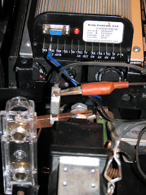
PakTrakr
The PakTrakr has been really useful for gathering all kinds of information: amperage, battery voltages, kW usage, etc. Unfortunately, it's not working quite as smoothly as I had hoped. It could be user error, but I've had problems with the following:
  • Battery voltage gauge indicates almost empty while batteries are nearly full.
  • The LCD screen has blanked out while under medium to heavy acceleration.
  • The entire module has reset while under heavy acceleration.
In the PakTrakr manual, it does state the batteries must be fully charged before plugging in the PakTrakr. The battery gauge showing empty instead of full could therefore be my fault, as I'm not totally sure what "fully charged" is for my system. A 12-volt AGM battery can apparently hold around 12.8 volts under normal conditions, so six of those make for 76.8 volts. However, since it reset on me mid-ride the other day, it now thinks my whole system is overcharged. =/ I do and have had the module set to AGM batteries, so I know it's not the case that it thinks the batteries are flooded or some other chemistry. I guess I'll have to email the manufacturer or post on the forums to figure out what is going on.

Amps
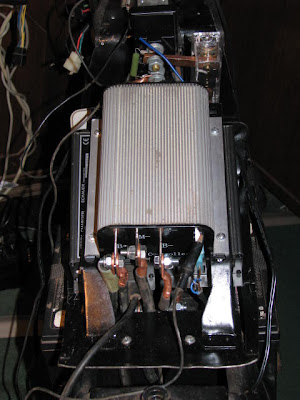
The amperage on the battery side of the controller has, of course, changed along with the gearing changes. At 5.667:1, I could slowly accelerate up to 25 or 30 mph without breaking 15 amps. At 4:1, I'm immediately at 30 amps or so and it's difficult to cruise at any speed while drawing less than 25 amps. Under hard acceleration, I used to pull maybe 110 amps at the most. With the new ratio, I got a reading of 150 amps. Keep in mind, that this is on the battery side. The motor is rated for a continuous 125 amps with bursts of up to 300 amps for no more than 30 seconds or so. The reduction in leverage is very apparent, both in these values and in the physical feel and pull of the bike. For my use though, it's worth having the top speed where it is now, instead of all that acceleration. I plan on trying to take care of this batch of batteries as much as possible, anyway.

Watts
I finally got a chance to gather a couple readings of kW usage as well. I never checked this with the original gearing, but the new setup resulted in 3.5 kW at around 25 or 30 mph and 5.4 kW at a steady 50 mph on level road.

3.5 kW / 30 mph = 3.5 kWh / 30 miles = .11667 kWh/mile = 116 Wh/mile = 72.5 Wh/km
Similarly, 5.4 kW at 50 mph is 108 Wh/mile = 67.5 Wh/km
I am not positive whether or not these calculations are correct, but they do seem reasonably close to that of other bikes of similar design.

Battery charging and discharging:
Below is the log that I've kept on battery charging discharging. This may or may not be terribly useful just yet, but in case any of the batteries don't last like the others, I'll be able to see if it was destined to or if I did something wrong.

SC = Start of Charge
EC = End of Charge
SR = Start of Ride
ER = End of Ride
BC = Battery Check

Act. Y M D h m B1 B2 B3 B4 B5 B6
Pack
State Odom Ratio
SC 10 8 19 22 17 11.5 11.7 11.6 11.7 11.8 11.8
70.1

39.2 5.7:1
EC


76.7

39.2
SR


76.8
resting 39.5
ER 10 8 22 19 00 11.7 12.0 11.9 11.8 11.9 11.9
71.3

68.5
SC 10 8 23 21 00


68.5
EC 10 8 23 23 30 12.4 12.6 12.5 12.4 12.5 12.5
74.9
resting 68.5
SC 10 8 24 20 40 12.2 12.5 12.4 12.3 12.4 12.4
74.2
resting 68.6
EC 10 8 24 21 40 13.0 13.3 13.2 13.0 13.1 13.2
78.8
charging 68.6
EC 10 8 24 22 25 12.5 12.8 12.6 12.5 12.6 12.7
75.6
resting 68.6
SR 10 8 25 19 45 12.4 12.6 12.5 12.4 12.5 12.6
75.0
resting 68.7
ER 10 8 26 01 00 12.0 12.3 12.2 12.1 12.2 12.2
72.9
resting 80.6
SC 10 8 26 18 35 12.0 12.3 12.2 12.1 12.2 12.2
72.9
resting 80.6
EC 10 8 26 21 15


84.4
charging 80.6
EC 10 8 26 23 05 12.6 12.9 12.8 12.7 12.7 12.8
76.5
resting 80.6
SR 10 8 27 07 40


resting 80.6
ER 10 8 28 00 05 12.1 12.4 12.3 12.2 12.3 12.3
73.6
resting 91.1
SC 10 8 29 20 13


91.1
EC 10 8 29 22 00 13.1 15.7 15.2 13.2 13.4 13.5
84.1
charging 91.1
EC 10 8 29 22 50 12.5 12.9 12.7 12.6 12.7 12.8
76.2
resting 91.1
SR 10 9 18 00 28 11.8 12.5 12.4 12.3 12.4 12.4
73.7
resting 91.2 4.0:1
ER 10 9 18 01 25 11.5 12.2 12.1 12.0 12.1 12.2
72.1
resting 100.5
SC 10 9 18 13 55 11.5 12.2 12.1 12.0 12.1 12.2
72.1
resting 100.5
EC 10 9 18 16 10 12.3 12.2 12.1 12.0 12.1 12.2
72.9
chrg B1 100.5
EC 10 9 18 16 50 12.0 12.2 12.1 12.0 12.1 12.2
72.6
resting 100.5
SC 10 9 18 17 00 12.0 12.2 12.1 12.0 12.1 12.2
72.2
resting 100.5
EC 10 9 18 19 00 13.0 13.3 13.2 13.0 13.1 13.3
78.9
charging 100.5
SR 10 9 18 19 15 12.5 12.7 12.6 12.5 12.7 12.7
75.6
resting 100.5
ER 10 9 18 19 47 12.2 12.5 12.4 12.3 12.3 12.4
74.0
resting 105.2
SR 10 9 20 17 50 12.1 12.4 12.3 12.2 12.3 12.4
73.7
resting 105.2
ER 10 9 20 19 00 11.9 12.3 12.2 12.0 12.2 12.2
72.7
resting 110.1
SC 10 9 20 20 00


110.1
EC 10 9 20 22 00 13.0 14.6 13.6 13.1 13.6 13.6
81.2
charging 110.1
EC 10 9 20 23 00 12.4 12.7 12.6 12.5 12.7 12.7
75.5
resting 110.1
SC 10 9 22 17 40 12.2 12.6 12.5 12.4 12.6 12.6
74.9
resting 110.1
EC 10 9 22 18 40 12.9 12.6 12.5 12.4 12.6 12.6
75.6
chrg B1 110.1
SR 10 9 22 19 05 12.5 12.6 12.5 12.4 12.6 12.6
75.0
resting 110.1
ER 10 9 22 20 47 11.9 12.2 12.1 12.0 12.2 12.2
72.5
resting 121.4
ER 10 9 22 23 10 11.9 12.2 12.1 12.0 12.2 12.2
72.6
resting 121.4
BC 10 9 23 17 45 11.9 12.2 12.1 12.0 12.2 12.2
72.6
resting 121.4
SC 10 9 23 17 50 11.9 12.2 12.1 12.0 12.2 12.2
72.6
resting 121.4
EC 10 9 23 23 00 12.8 12.2 12.1 12.0 12.2 12.2
73.5
chrg B1 121.4
EC 10 9 24 00 05 12.3 12.2 12.1 12.0 12.1 12.2
72.9
resting 121.4

I'm still learning plenty about the batteries and my chargers. The chargers are supposed to be intelligent enough to do a 3-stage charge and turn their LEDs green when in the float-stage. This has never happened and makes me worry about A) the chargers being wired and used in a manner for which they were not engineered or B) the two large sparks upon finally assembly having screwed them up. I guess option C would be that I've never absolutely fully charged the battery pack halves. This would actually be good news I think. What's strange is that the PakTrakr shows some batteries slowly being charged up to 12.9 volts, while others batteries show to be charging up to 14 volts and higher, and accelerating upward in charge voltage. For example, look at August 29th, during charging (EC.10.08.29.22.00). Here, batteries 2 and 3 were very far above 13 volts, which was scary and I have no idea if this is dangerous or normal. Maybe they would eventually get float-charged by their charger, once B1 matched them.

Balancing:
Balancing the pack is also a new adventure. I purchased a 12 volt battery charger from Walmart which stated it was compatible with AGM type batteries. So far, batteries 1 and 4 have turned out to rest just a bit lower than the others. Attempts to bring B1 up with the likes of B5 and B6 haven't exactly been successful just yet. However, I haven't let this charger, like the other on-board chargers, reach what it considers fully-charged. I still need to learn how sensitive the batteries really are and whether I'm hurting them in any way. Once again, this will take research and assistance from the forums probably.

Other Notes:
I accidentally got caught in the rain the other evening - No failures of any kind, but how much water can the ME709 really take in those vents?

Inspecting the bike has been more critical than I expected. Had I inspected it closer from day one before each ride, I would have avoided several headaches and delays. Far too many close calls in this area.

Also, for the record, I would like to say how much I enjoy the correctness of the term "motor-cycle". Naturally, I never thought of it as inaccurate before stumbling into the EV scene, but how cool is it that my bike really is a motor cycle, not an engine cycle.

-Colby

Thursday, August 19, 2010

First Impressions

I rode the bike around my neighborhood all evening yesterday. The odometer and speedometer are primarily in kilometers, so I'm still deciding what unit of measurement to work in. I'd like to keep a pretty close log of rides and data to try and track the health of the system for a few months.

Ride 1StartStopMax
Odometer (km)1237
Voltage7669
Batt. Amps100?
Speed (mph)40

25 km is 15.5 miles, so I'm really happy about the range so far, even if I averaged only 20 or 25 mph. It's certainly no worse than my worst-case scenario. It will interesting to see what range I can get at an average speed of 40 or 50 mph though.

I tried to keep an eye on the PakTrakr:
I could easily accelerate and keep the battery-side amperage at or under 10 amps.
I could maintain 25 mph at about 4 amps.

The PakTrakr seems a bit confused about my battery State of Charge (SoC) at the moment. I followed the instructions and changed the chemistry setting to AGM, which I know to be accurate. Still although it can accurately report the pack voltage, it shows the SoC as being 72% when the pack is at 77 volts. The fuel gauge mode shows a mostly empty tank even though the pack is still around 71 volts. It could be user error - I've reset the display by unplugging the remote several times. As far as I know, everything else is working fine. I love the thing already, but I need to try and correct the issue.

My chargers are not working like I expected either. I'm not sure why, but they don't seem to shut-off, or rather, go into float mode when I think they should. Then again, I'm still a bit unsure what voltage my pack should have when "fully charged". If a fully charged AGM 12 volt battery actually reads 12.8 or 12.9 volts, then my batteries are spot on. The charges just seem to stay on full-blast (and stay hot), even once the pack has reach 77 volts (according to the PakTrakr). It might be that the two, 36 volt chargers are wired in series practically, and so they're interfering with each other's monitoring logic. I guess I could try charging the pack in halves to see if their behavior changes.

The controller only threw one error message while I was actually out riding. This too was probably my fault. After coming to a stop, I went to make a sharp right, which led to a down slope. There was a chug-a-chug feeling that may be mechanical on the bike between the motor, chain, wheel and swing-arm. I felt for a moment that the bike was trying to go sporadically, although not with full-power like a run-away. Somewhere in the chugs and whatever strange throttle inputs I gave it, the controller detected a problem. I only wish I had written the error code down, in case it occurs again or was something I haven't seen yet. A simple re-boot allowed me to keep going. I checked for damage or heat but found nothing. That was mid-way through the ride and it didn't hiccup, so to speak, any more.

In the end, it was super cool cruising around and turning some heads last night. Next thing to do is solve the few remaining mysteries and start people-proofing it so I can leave it in public with confidence.
-Colby

Wednesday, August 18, 2010

Road Testing

The bike is now in the city and completely legal, so it's time for road testing.

I'm anxious to find out some stats.
Sitting still, the PakTrakr reports a draw of .2 amps.
With the LED Truck-Lite on low-beam, it shows .4 amps.
High-beam makes it .6 amps.
A quick spin around the neighborhood showed 94+ amps on acceleration but only 29 amps for steady cruising.

It's seriously fun to ride.
It is almost like floating down the road. It's pretty quiet of course, but there is a nice electrical whirring created by the motor at 25 mph. I may need a different drive sprocket to achieve 55 mph. The mirrors may need to be relocated or replaced for safety. The license plate may need to be relocated for preference. Overall though, it's a really cool way to get around.

Pictures and stats to come soon!
-Colby

Monday, August 9, 2010

Sevcon DC Converter

A Small Problem:
My bike has a 12 volt electric system for the lights, gauge cluster and horn. I used a 72V to 12V DC converter to supply power to that 12 volts system. I chose the Sevcon 300W converter and ordered it from ElectricMotorsport.com. My only complaint is that I was not provided a connector or a specifications sheet for the device.

The Solution:
Well, the spec sheet .pdf is easy to find at the manufacturer's website:
The plug was not as easy to find, but I gathered enough clues until I nailed it down. The converter connector is a Mini-Fit, Sr. housing, made by Molex. There are technically three different kinds of housings, but there is only one receptacle that fits all three, so you can place an order with confidence. The only catch is that it may not come with the actual conductive terminals - depends on where you order it from. Luckily, I knew my would not come with terminals, and I was able to find them too.
Part Numbers:
I ordered my plug and terminals from Allied Electronics in Fort Worth.
The Molex part number for a plug is 42816. (need 1)
The Molex part number for a female terminal is 42815. (need 4)
The Allied Electronics part number for a plug is 863-1427.
The Allied Electronics part number for a female terminal is 863-1464.

Additional Info.:
Be aware, if you order from somewhere else, there is an entire series/family of Mini-Fit connectors which include single-row / dual-row and 2 through 8 circuit variations. Also, there is a clip which is molded onto single-row connectors which serves to stop the terminals from backing out. For the record, the receptacle I needed for the converter was a single row, 4 circuit connector. Since it didn't include terminals, I ordered 4 terminals for size 14 or 16 AWG wire. The whole thing goes together really easily and makes a reliable connection to the converter, which was great to see.

Here's the search string to find all members of the series in Allied Electronics' online interface.

Here's a .pdf which explains the parts with images, in case that helps clear up any confusion.

-Colby

Sunday, August 8, 2010

First Test Drive

The bike was finally at a point we could test drive it this weekend, so that's exactly what we did.
It rode pretty smooth, very quiet, and everything went just great.

Check it out:


Several things remain, but registration and inspection are very near.

-Colby

Wednesday, July 14, 2010

Controller Grounding

After wiring up the controller, we found that the chassis was being grounded somewhere. We weren't sure if this was normal or not or good or not so I researched it.

Kelly User Manuals:
Version 2.3 of the Kelly user manual specifically mentions not connecting B- to GND on pages 10 and 11 (sideways footnote), but in this instance, I believe they are referring to the GND pin on the front and rear panels which is simply a ground connection for input and output sensors. So this doesn't answer my question. However, version 3.1 of the Kelly user manual specifically mentions it being preferable to wire B- to the chassis on page 9.

The Forums:
I signed up for ElMoto.net recently and today I was in the chat room when a couple guys joined: RC and Guff. We got to talking about my bike and I asked about this issue. Each said their bike has neither the low-voltage system (12 volts) nor the high-voltage system (72 volts in my case) grounded to the chassis. When I asked about how to accomplish that with respect to the high-voltage components, at least two solutions were mentioned. I guessed that plastic screws / washers were required, because that's what Lennon did. However, RC mentioned using polycarbonate board, which serves as an insulator. Without using special hardware, a component can be mounted to a sheet of polycarbonate or something like "garolite" and the sheet then mounted to the chassis. This isolates the two, so even if the component isn't internally isolated from its outer casing that won't leak on the bike chassis. For the low-voltage components, I've read posts about running new ground wires to the lights and horn instead of using the chassis.

After chatting with them a while, I searched more and found these threads agreeing with their input
Additional threads:
  • ElMoto.net, Thread 2167 - Main high-voltage components / grounding
  • DIY Electric Car, Thread 14817 - Kelly KDH14500 wiring / grounding
  • V is for Voltage, Thread 4066 - Kelly refund & exchange policies / testimonials
That last thread mentions something interesting: The author of post #5 in states that High-voltage Kelly controllers are not insulated from the chassis ground while low-voltage controllers are insulated from the chassis ground. That might have been the case in July of 2008, but I'm not sure it is still reliable information, and I don't know which controllers he's considering high or low-voltage.

The issue:
Safety is the main deciding factor here. If the bike chassis is grounded to the pack, then (depending on exactly what you touch) you could complete a circuit with your body or with a tool and damage yourself and your bike. I don't feel great about ignoring what the controller manual says, but I'd rather the bike be safe to work on than dangerous because of what could be a poor translation in the manual.

For the record:
Strangely, while researching, I stumbled upon a thread about using a Kelly controller in some Z20 model scooter, and then a completely separate thread referencing the first, concerning (rather questioning) Kelly, their product and their service.
  1. V is for Voltage, Thread 3714 - Moving to a Kelly controller for Z20b
  2. DIY Electric Car, Thread 16961 - Kelly controller quality
I guess the guy whom started that thread on DIY was in a hurry or failed to notice the picture was not of a Kelly manufactured model, but of some controller being provided for electric scooters by some dealer. Anyway, for the record, I've had no problem with Kelly, nor with my Kelly controller (it's been in use for one week). While chatting on ElMoto.net, one member mentioned his Kelly controller has been working just fine for 6 months. My only complaint is about the lack of clarity within Kelly's manual and wiin replies to questions via email. I've emailed sales@kellycontroller.com a couple times regarding both sales and technical wiring support and have always received quick responses. If you can be patient and don't mind reading and thinking a bit, I imagine Kelly will do right by you. If you do email them, use direct and very clear language to ask individual questions. That's what has worked for me. I haven't read about any instances of faulty Kelly controllers, though you do have to seriously study the user manual provided. Even in cases where a controller gets cooked because of user error, it seems they often replace the controller or offer to repair it, usually only for the cost of shipping.

On another side note, ElMoto.net has been a great resource so far. The users seem down to earth and willing to help newbies like myself. There's a lot to figure out, and it seems every bike is slightly different. Starting a thread for my project has helped quite a bit already.

-Colby

Tuesday, July 13, 2010

Rotation

It was a big day for the bike.
The motor turned for the first time today.

I've been making good progress at figuring out wiring details in the past weeks and we finally got to a point where we could pretty safely test the contactor, controller, motor and throttle. It seems to work, which is really exciting. The controller was programmed to greatly limit is output and after minor troubleshooting, the controller's LED showed it was ready and without errors. It's a bit jerry-rigged at the moment, but we'll be making more permanent connections soon in order to do test runs and get it inspected.

Here are a couple pictures of the controller. Like I said, jerry-rigged for testing!

Rear Panel:


Front Panel:


-Colby

Tuesday, June 22, 2010

Pre-Charge Resistors

The name itself says a lot, but honestly, until I went to wire up my motor controller for the first time, I had no idea I needed one, nor why.

What:
The pre-charge resistor does just that - it allows for charging of the capacitors in the motor controller prior to the closing of a of high-current switch or contactor.

How:
Simply put, the pre-charge resistor allows the motor controller capacitors to be in a circuit with the main battery pack even though the contactor is open (not completing a circuit). This by-passing of the contactor allows the motor controller capacitors to stay charged, sometimes called "fully formed". There's a catch involved here related to the importance of selecting the correct resistor for a certain system, so please read this entire post to be aware of important details.

Where:
The pre-charge resistor is wired "across" the main terminals of the contactor. That is (equivalently), one end of the resistor on the battery's positive terminal and the other end of the resistor on the controller's positive battery terminal. Being in parallel with the contactor allows for the "bypassing" (as I call it) of the contactor. Check the documentation on your own motor controller as some may already have a pre-charge resistor internally, but my Kelly KD72401 does not.

Why:
When a contactor "closes" (to complete a circuit), the amount of current which immediately tries to pass between the contacts affects the life of those contacts. In the case of EVs, uncharged capacitors in a motor controller can draw such an in-rush of current, the contacts will arc, creating pits in their surface (which reduces usable contact surface) or perhaps even welding the contacts together. Furthermore, the capacitors themselves can be damaged by such an in-rush current. On the other hand, capacitors that have been mostly pre-charged will draw a much smaller in-rush current, which limits arcing of the contacts and increases the longevity, reliability and performance of the contactor as well as the motor controller.

Don't miss the point:
It is possible to render this component useless so please still be cautious. This is exactly why I like to know what each component does and how...

Many builders put a master on/off switch (in addition to the contactor) capable of handling 300+ amps for manually opening the main battery circuit as a safety measure or convenience. If such a master switch is present, it will of course allow the motor controller capacitors to discharge over time, which is probably normal. The only dangerous part is when the system is wired such that the contactor can be closed while the master switch is off. With the capacitors uncharged, if the contactor and then the master switch is closed, then the pre-charge resistor will not have an opportunity to function. The path of least resistance will be from the batteries, through the master switch, through the closed contactor, and straight into the capacitors. Those capacitors will attempt to charge almost instantaneously and may be damaged in the process.

One fix in this situation is to install another pre-charge resistor, this time for the master switch. This will allow the motor controller capacitors to always be charged and ready - making the contactor's job (and the controller's job) less stressful.


What exactly:
Now that we know their purpose and value, lets take a practical example for application to your own project.

According to the Alltrax Lessons Learned document, the resistance of the pre-charge resistor should be selected based upon battery pack voltage. In my case, 72 volts implies a 1000 ohm, 10 W resistor. The resistor with which Kelly Controllers provided me is only a 300 ohm, 10 W resistor. To know whether or not that will suffice, I checked the following calculations:

Peak in-rush current can be determined by battery pack voltage divided by Equivalent Series Resistance (ESR) of the capacitor bank. This might be measurable on the controller with a digital ohm-meter. Assuming the bank is made of 10 capacitors, each with a resistance of .05 to .5 ohms, the bank's total ESR would be .005 to .05 ohms. Thus, without the pre-charge resistor, 72 volts / .005 ohms = 14,400 amps. The capacitors probably aren't rated for that, so even though it's just the peak and only experience for an instant, it could cause one or more capacitors to short-out internally.

With the pre-charge resistor, the peak in-rush current is 72 volts / 300.005 ohms = .24 amps. Therefore, the peak dissipation in the pre-charge resistor is 72 volts * .24 amps = 17.28 watts.
That's almost twice the 10 watt rating of the provided resistor, but it might be alright since that's just the peak dissipation which falls quickly from 17.27 to 10 watts in around .275 seconds.

Using the rule of thumb that a capacitor is 99.3% charged after 5RC seconds lets us estimate how much time the motor controller capacitors should be given to be (close to) fully charged, where R is resistance and C is capacitance. Assuming the motor controller has a total capacitance of 3300 uF, 5RC = 5 * 300 ohms * (3300*10^-6 farads) = 4.95 seconds.

One member of the diyelectriccar forum suggested selecting the pre-charge resistor based on the size of the battery pack - that is, based on its voltage. He stated a resistor with 1 ohm for every 1 volt of potential difference will result in a current of 1 amp (72 volts / 72 ohms = 1 amp). Also then, 72 volts * 1 amp = 72 watts, which sure sounds like a lot more power dissipation. I don't know much about the chemistry and makeup of resistors, but the guy stated that because the pre-charge was going to take so little time, a sand-filled 10W resistor would probably work. The time calculation checked out, as 5RC = 5*72 ohms *.003300 farads = 1.19 seconds, but I don't know for sure that the resistor I was given is sand-filled. Then again, I'm not sure about my motor controller's total capacitance either, so there are still plenty of variables.

Conclusion:
In the end, the objective is to protect your investment, as well as your own well-being. The critical issue is to make sure the controller always has an opportunity to pre-charge (at an appropriate rate and as completely as practical) to full drive power before closing that last high-current switch.

References:

Graphing / Analysis of RC Circuits

Wednesday, June 16, 2010

Bike Week

Bike Week was great. I took off a few days from work and spent them working strictly on the bike.


We definitely made great progress:
  • new front "dash" created from scratch
  • LED headlight is mounted
  • LED turn signals are mounted
  • gauge cluster is mounted
  • battery cables created / used
  • Kelly controller programmed
  • throttle connected for the first time
The bike hasn't rolled under its own power just yet. Several questions and uncertainties were brought to light regarding exactly how to wire the controller, so we concentrated on other things and made the best use of our time. The following issues or questions came up:
  • wiring my controller specifically
  • pre-charge resistors
  • contactor coil diodes
  • contactor behavior / operation
  • battery installation / maintenance
  • charging standards / connectivity
  • throttle resistance readings
  • language barrier surrounding Kelly controllers
These still remain to be tackled:
  • Tank component mounting
  • Turn signal lighting
  • All wiring
  • Testing / tweaking
  • Insurance
  • Registration
  • Inspection
I'll try and cover some of these as individual posts in the near future to organize what we have now learned first-hand, and that of others. It was fun investing time into this and figuring out how to overcome some pretty tricky design challenges. I'm really looking forward to finalizing in great detail my understanding of all the components and how they work - That and taking a spin around the block on my own, custom electric motorcycle.
-Colby

Saturday, June 5, 2010

Quick Update

I've got a new picture of the bike.
As you can see, the seat has been shortened, the fuel tank is back (innards reworked), the chain mounted, and the electronic throttle is attached.


I love the way this looks, to be honest. It's extremely close to what I envisioned almost two years ago.

Nothing has been wired up just yet, but that should change in about one week's time. I've taken a few days off from work in order to concentrate on the bike with my dad. The next primary objective is to get it running under it's own power. The secondary objective is to get it as close to inspection-ready as possible.

In preparation, I did a bit more research on inspection requirements and ordered a Truck-lite 7" round LED headlight. As far as I know, this is the only DOT approved LED headlight on the market. It's pretty important to me that at least this be completely legal. It was expensive, but I think it will be worth it. I also think it'll look just fine on the front of the bike, but we'll find that out soon enough. The turn signals and license plate bracket are another issue. I'm not sure I'll be able to get parts delivered on time, but we can work on mounting points even without the exact components present. The license plate also needs a light and a place for an inspection sticker, come to think of it.

I'll be thrilled to get the thing rolling on its own and wired up a bit. We'll worry about the specifics of insurance and registration when we get there.
-Colby

Monday, May 24, 2010

Wiry Information

I've been doing a fair amount of research on wiring in the past week. It's not a simple task, figuring out what will work safely and reliably. Even now I am not absolutely confident in my decision, but at least I feel like I know what to try and what not to try.

Note: What I discuss here applies to DC and may only partially apply to AC systems.

What I found out:
I went looking for a chart saying voltage X with a maximum amperage Y requires wire Z. That doesn't really exist - mainly, because every situation is unique. There are several charts that do give you a sense of the tolerances, but please use that information carefully. A minimal list of factors that affect the accuracy of any figures you may find are as follows:
  • AC vs. DC
  • length of the wire
  • Amps / circular mils
  • Insulation rating
  • The immediate environment of the wire
  • Acceptable voltage drop
  • Voltage rating of the wire
My questions from my last post were in regard to the chart at http://www.powerstream.com/Wire_Size.htm I was asking two main questions about main drive system wiring.

The wiring can vary on either side of the controller. Because the motor controller is just a power-converter, it takes in just as much power as it puts out. The key is that it does its input and its output over different, and varying lengths of time. The battery-side of the controller will not be handling large amperages (maybe 70 amps max for me) while the motor-side could see much higher current (limited to no more than 300 amps for 1 minute by my motor). This is most obvious at peak numbers of course, but still applicable at the continuous ratings for my components. The point is: Yes, different kinds of wire could be used to handle the different kinds of power on either side of the controller. Each wire or set of wires could be size appropriately to its own set of influencing factors. You don't have to though. You could use one size as long as it is rated for the most strenuous parts of the system. It means carrying around a little bit more weight and maybe spending a few cents more for both the wire and hardware to couple it to the battery pack, but that's about all it impacts.

As for what gauge to use, now that's kind of tough to answer. As you may know, I'm basing most of my bike on Lennon Rodger's eMoto. Naturally, I looked at his page and found that he used 4 gauge (AWG) welding cable. When I looked up the specs for 4 gauge wire on the PowerStream chart, I was confused. Firstly, there were multiple amperage ratings, but reading a bit helped. The left amperage column is called "maximum amps for chassis wiring" and the preceding paragraph explains that it is A) a conservative rating and B) for wiring in air, not bundled with other wires. Meanwhile, the "maximum amps for power transmission" column is based on the700 circular mils per amp rule.

What the heck is the 700 circular mils per amp rule?
Let me try to build up to it...
Mils does not mean millimeters. Mils means thousandths of an inch (.001 inches). Circular mils can be abbreviated CM and is used as a unit for measuring circular area, but there's a twist in the definition:
  • Circular mils refers to a circular area in terms of the square having sides with length equal to the diameter of said circle.
I suppose a picture would help a lot right about now:
Source RF Cafe

So basically, it's a very rough expression of the area of a circle. We now know that the area of a circle expressed in circular mils is not the exact area of that circle at all. It's an approximation that avoids reference to Pi. And just for the sake of confusion, (somehow) MCM means thousands of circular mils. That is, an area of 400 MCM = 400,000 CM.

Applying our new understanding:
The rule is talking about how much surface area is present for current to flow through. Obviously, since we're talking about circular surface areas, it is in reference to the cross-sectional area of the wires. You may find information about surface areas in regard to a wire with AC, but be careful, as that may be in reference to the longitudinal or "skin" surface area, instead of the "face" or "end" surface area of the wire which I've been describing here.

The 700 circular mils per amp rule, therefore, means that 700 CM of cross-sectional area are being taken into consideration for each amp in the wire. In other words, each amp of load adds roughly .0007 square inches to the cross-section of the wire.

Take a specific example:
PowerStream shows 1 AWG wire as being capable of carrying almost 120 amps according to 700 CM per amp rule. It shows 1 gauge as being .2893 inches in diameter. Since 1 CM is .001 inches, we can divide .2893 by .001, indicating 1 gauge wire is 289.3 mils in diameter. Using our picture and definition, we can put that in terms of CM simply by squaring it. Thus, 289.3 mils * 289.3 mils = 83694.49 squared-mils or CM. Now, we check to see how many amps we can put through a wire with that kind of cross-section by dividing it by 700 CM. 83694.49 CM / 700 CM per amp = 119.56 amps. Cool beans.

Cross-referencing our earlier statement, if each of the 120 amps adds .0007 square-inches (according to the 700 CM rule) to the wire, then the wire's cross-section has an area of .084 square-inches. The chart stated the diameter of 1 gauge as .2893 inches, so we see that .2893 inches * .2893 inches does in fact give us .08369 square-inches. Double cool. That's all without using Pi, so even though it is nice that it matches, do remember that it's not a precise measurement of the cross-sectional area.

After all that, you should know that 700 CM per amp is a "very, very conservative" rule of thumb. Additionally, the shorter the wire, the less area you have to provide for each amp. For my bike, hopefully I'll be dealing with no more than two-foot lengths of high-power wiring. I've read that with such short distances, a rule more like 200 or 300 CM per amp is acceptable. If that's true, then we can safely use a slightly smaller wire. Given that my motor is rated for a continuous load of 125 amps, if I used the 250 CM per amp rule, 125 amps * 250 CM / amp = 31250 CM. Since 1 CM = .000001 square inches, that is .03125 square inches. The diameter of a wire with that surface area is then the square-root of .03125 square-inches, which is .17677 inches. Referencing the PowerStream chart once again, that does fall pretty close to 5 gauge, which is a reasonably accurate result considering Lennon's choice of 4 gauge.

Voltage drop:
The voltage drop along a wire depends on the resistance between the source and the load. All wire resists charge flow and this resistance reduces the amount of voltage being provided further down the circuit. It comes down to how electrons flow through the wire really, so considering water flowing through pipes can help here. The longer the wire, the more electrons there are in the way causing increased resistance. However, the wider the wire, the more electrons are available to carry the current and therefore decreased resistance. Furthermore, all materials have their own unique makeup so the exact resistivity and operating temperature of the conductor in use will definitely have an impact.

These factors are represented by the relationship R = p L / A, where R is the resistance of the wire in ohms, p (rho) is the specific electrical resistance of the conductor in ohm-meters, L is the length of the wire in meters, and A is the cross section area of the wire in square meters. Keep in mind that voltage is actually a potential difference, so L is usually twice the one-way distance between source and load so as to incorporate the losses to and from the load. Also note that temperature will affect the electrical resistivity of the metal.

The amount of voltage drop obeys V = I R, where R is the resistance of the wire in ohms, I is the load current in amps and V is the resulting voltage drop in volts. Based on that relationship, we know how voltage drop will fluctuate, given the details of the circuit. As an example, when the current flowing into or out of the controller varies, we know the voltage drop will vary. Similarly, as the wire heats and cools, it's resistivity will change, resulting in slight variances in voltage drop.

Having a larger amount of supply voltage doesn't change the resistance of the wire, nor the current drawn and therefore does not affect voltage drop. What a larger supply voltage does affect is the percent voltage drop, because it is a ratio of voltage available to the load versus source voltage. That is, if 72 Volts is supplied, and the wire causes a drop of 1 volt, then the ratio is 1/72 which is .01388. In terms of voltage loss, that's 1.38 % which, according to my reading, would usually be very acceptable.

Most of what I found on voltage drop spoke about limiting the percent voltage drop to an acceptable level. The idea is that the load device should be provided an acceptable voltage after the drop caused by the wires. Outside of that acceptable input-voltage range, you're probably sacrificing device life or efficiency or both.

Insulation:
Insulation protects a wire, but can only stand so much heat. If more heat is being generated than the insulation handle, then obviously, it will fail (melt). Apparently, most battery cable has PVC insulation. Most welding cable has rubber insulation and may handle 600 volts. Then there's locomotive-grade DLO cable which may handle 2000 volts. I looked up a few specs for battery cable available at a local auto-parts store only to find that the insulation was rated for a maximum of 60 volts. I know 72 isn't too much of a stretch, but as usual, I'd rather be safe than sorry. I'll probably go with a welding cable instead of at least 4 gauge.

Ideally, wires would be rated for some overall power, instead of just a maximum current. However, as we've seen there are a lot of factors which make that kind of rating difficult to determine. In the end, I'll probably go with two sizes of cable, for the two sides of the controller. Something like 4 or 5 gauge welding cable on the battery-side, and 3 or 4 gauge welding cable on the motor-side of the controller.

References used:
Other news:
Hooper Imports served me well. I got my parts and they look great. I'll have to report back one more time when I get a chance to actually put them on the bike. The point is they sent exactly what I ordered, and they did so quickly, with no fuss and no issues.

Tuesday, May 18, 2010

Back on Track

The Spring semester is over. It went well. Now where was I?

Oh right - So here's the deal:
  • I'm about ready to wrap this project up.
  • It's summer time and I don't have school to worry about.
  • The bike is more or less mechanically, ready.
  • The really detailed work is what remains.
...So I do believe there's plenty left to learn.

The foam gas-tank replacement didn't pan out. Although aesthetics wasn't a huge concern, using that shell and arriving at something functional and appealing just felt afar off. We turned back to the original tank and my Dad did some intricate metal-work in order to have something compact, workable, and down-right nice looking in minimal time. This is the space that will contain the chargers, DC converter, motor controller, main contactor and a fuse or breaker.

So, now that serious electrical wiring needs to be done, I have several questions concerning the new electrical system being installed on the bike:

What gauge wire should I use for my bike?
Lennon used #4 welding wire, which should be the same as size 4 AWG. But how come all the charts I find out there for AWG show very conservative numbers? For example, this site shows #4 wire being capable of only 135 or 60 amps, depending on use (what's the difference between chassis wiring and power transmission, anyway?). A good point my Dad brought up was that there's only so much surface area at our disposal on the controller terminals and that will absolutely place an upper limit on the size of wire we can expect to need.

Will the battery side of the controller need a different gauge than the motor side?
I haven't posted yet about how my motor controller works, but I some-what understand the principle at work, and that the battery side won't (or shouldn't) see more than maybe 140 Amps, while the motor side could see 300+ Amps. I know selecting too large a gauge is not a serious problem, so I guess I'm asking whether or not there's a reason (and what that reason is) to use separate gauges for each side of the controller.

Can my proposed charging system be implemented?
This is not a question of how well will it balance the batteries, but rather, can it work at all. The chargers have been tested and seem to work fine. We just aren't perfectly clear about whether or not we can leave them connected when the bike is being driven, or if we should add a component or place an existing component such that some charging circuit is broken in order to operate the vehicle. I expect it depends on the exact method in which the chargers are wired to the batteries as well as how the chargers are wired internally, so we're just still researching and figuring this out.

Here's what remains to be done:
  • Sort out a wiring diagram for our specific bike.
  • Research, select and install electric drive system wiring
  • Adjust and install drive chain
  • Test throttle switch
  • Program controller
  • First test of electric drive system
  • Break-in the motor
  • Install PakTrakr
  • Re-cloth modified seat
  • Remove and/or treat rust
  • Finish and paint component shelves.
  • Final paint and assembly

Oh, I did want to mention how I found a supplier of certain Lifan parts. Lifan being Chinese makes it kind of a big deal to have a good supplier of parts here in the US. I ordered parts from Hooper Imports. They're in Redmond, Washington and seem to be very genuine and rather-closely tied to both Lifan and American Lifan out of Dallas, Tx. Trust me, I would have ordered parts from American Lifan, considering their convenient location, but their online parts-store has been "coming soon" for quite some time now. I suppose I could have called, but I didn't have part numbers to reference. I feel good about my order to Hooper Imports, and I look forward to verifying I ordered and received the correct items.

I wish I had an image or two to show the state of the bike, but I'll be sure to snap a few in the coming weeks. I may take a few days off work to help get as much of this done as possible. Maybe by the end of June, we'll have something ridable and almost licensable.

-Colby